Name of solutionRocket Stove
Category of solution
> Cooking / Heating [LINK] |
PDF version to download
Related Energy School
> Thermal energy | |||||||
Short introThe rocket technology is about producing high temperature heat (700-1100°C) with a clean burn (low emissions of smoke and greenhouse gases) while using minimal amounts of fuel. It’s a thermal energy solution that is cheap and quite easy to build but can be applied to cover many different needs when and where heat is wanted. Applications can be as a stove, an oven, a space-heater or a water-heater (connected to an accumulator tank or radiator system). The effectiveness comes from understanding thermal dynamics and using specific dimensions and proportions when building the rocket. One of the most simple ways of using the heat from the rocket is as a stove, placing a pot or pan directly on top of the rocket in order to cook food, boil water or other similar usages. The other, slightly more complex modifications of the rocket can be found on the platform, with the rocket mass heater perhaps being the most effective usage of the rocket. General idea of the solution
|

|
Complexity and cost of building and operating
Complexity of building and operating:
Medium (does not require special skills to build, low levels of maintenance)
Cost:
Medium (50-200 EUR)
Medium (does not require special skills to build, low levels of maintenance)
Cost:
Medium (50-200 EUR)
Materials, skills and tools requiredSkills Building a rocket-stove does not really require any special skills or building experience, even though it is always helpful to have some experiences when building (e.g. working with natural materials, bricks, metal or making molds for casting). Tools It is good to have a basic setup of hand tools when starting a build of a rocket. Depending on which solution you choose, and with which combination of materials, different tools may be needed. Here is an example for building one of the more common solutions, using fire bricks and clay-straw insulation:
Materials A rocket-stove can be built using different materials and different combinations of them. The important properties of these are that they can withstand high heat without deforming or degrading (refractory), and that they have enough insulating properties where needed. Trapped air (<4mm pockets) will ensure good insulation without convection in the material. Here are some examples of materials and how they can be combined:
If wanting to build other rocket solutions than a stove, there are also other materials involved, specific to the solution. More information on this will be found on the platform where other rocket solutions are presented. If using metal, use stainless steel. If and when using metal inside the rocket, or as a stove-plate, it is important to use a heat-resistant steel once the design is done (not prototype stage). This often mean that stainless steel (SS) is needed in order to ensure a long lifetime of the installation, even though SS is often quite expensive, more challenging to process (f.ex. welding or cutting) and can be difficult to find in scrap-yards. Optional metal to SS is 3CR12, which has similar properties but often half the price. If not using stainless steel in the system, an effect called spalling will likely occur. This is a type of rusting that breaks down the metal in a rather short period of time and happens when the steel is exposed to high temperatures (>500°C) in an oxygen-rich and carbon-low environment. Carbon is then extracted from the metal, causing it to flake and dissolve. If the metal is not insulated, this might decrease the effect of spalling as convection is cooling, but also means lost heat in the rocket. As any metal (mined material) should be viewed as a precious resource, we should perhaps try to not use designs where the metals are broken down and causing pollution, indicating that it is a less smart solution. This would also result in more work and repairs during the lifetime of the rocket. |
Tip! If using materials such as fire-bricks, sand-clay mortar and clay-straw insulation, the rocket can easily be de-assembled and the materials re-used. This can be attractive when you start building rockets and learning the process, without risks of unnecessary costs and use of resources. |
Description of the solutionHow it works
By building the rocket while using specific measurements and dimensions of the system, the rocket allows for 2 separate combustions in the same system, which results in higher temperatures, cleaner exhaust and less fuel. In the first combustion (A in fig,1 below), the gases are released from the fuel (C) and burned at 300 - 600°C. The non-combusted gases left from the first combustion in the burn-chamber get a chance to reach high enough temperatures (through friction in a limited, insulated space) in order for a second combustion to occur inside the heat-riser (B), before the heat/energy is being released and used at 700 - 1100 °C. By insulating the system and using the heat at the exhaust, less energy is “wasted” than in most traditional biomass stoves. 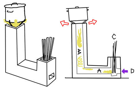
Fig, 1: How the rocket works
Why the name "rocket"?
The name Rocket has been given as the stove, when working correctly, sounds similar to a rocket or jet-engine as the air is being pulled and pushed through the system with high speed. If it doesn’t sound like a “rocket”, something is probably wrong. Spotting a ”wrong” rocket The rocket-sound is not enough though in order to determine if the dimensions are optimal and the rocket has all the properties that we seek. There are many descriptions of solutions posted online or in other places that may sound like a rocket, but are not following all the “rocket rules”. This often results in a lower maximum temperature, more wasted energy and more emissions. If f.ex. the heat riser seems very low, or the stove is made of uninsulated materials, we might think that the laws of physics are not fully respected and that optimal conditions are not met. These solutions might still be quite good, depending on conditions and needs, but it’s not the same kind of rocket that we are trying to make here. The important dimensions of a rocket The size of each stove is determined by the cross-area of its heat-riser. A size that is often used for large rockets is a round shape with a 20 cm diameter opening (8 inch), which equals 17.7x17.7 cm for a squared shape (314 cm2). If wanting a stove with less effect then the cross area should be decreased, which also results in less height which could otherwise be a limiting factor. Adjustments might have to be made in order to create a comfortable working height when cooking with the stove (standard height for a workable surface is approx 90 cm). This can be achieved either by burying the foundation of the stove in relation to the floor, or elevating the floor/ground. 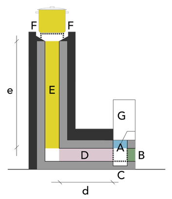
fig,2: The parts and dimensions of a rocket
A: Feed tube
B: Additional air intake and cleaning hatch C: Ash pit under fuel D: Burn chamber d: length < e/2 E: Heat riser e: height F: Exhaust outlet and stove surface G: Possible cover or storage/guide for fuels The grey layer is the internal building material and the darker layer is the insulation. These might be the same if using for example leca-blocks, adding both structure and insulation (the size of the cavities in the blocks should be small, <4mm, as convection and heat losses will most likely otherwise occur in the materials). The dimensions shown in the graph are the largest height-to-cross area ration. If the rocket has a 314 cm2 area, the ”ultimate” height of the cooking surface is approximately 160 cm, which of course is too much without adjustments of the base and smaller dimensions might be more suitable. Feed tube & air intake (A) The feed tube is where the fuel (braches, twiggs, pinecones, pellets etc) are inserted. The solution shown here is called a J-tube, which means that there is less need of pushing the fuel into the burn chamber as they burn and instead rely on gravity as the fuels are inserted from the top. If irregular branches are used, they might hook onto each other, and it is advised to have as straight pieces of fuel as possible. The height of the feed tube should also be kept low in order to ensure a good draft, not creating a chimney for heat to build up. Extra equipment (G) could be added on top of the fuel tube in order to stop air and flames to move up-ward and/or to support longer pieces of fuel (or a system for pellets or wood chips).
Extra Air intake (B) As the feed tube can get filled up, thus reducing the flow of air into the rocket, an extra air intake might be needed. This opening can also be very useful for cleaning out the burn chamber from ashes and other build-up. This extra intake might also be very much needed for a rocket that is placed indoors, as external heat then can be directed to the rocket through a channel, instead of it being taken from the inside, sucking cold air into the building. The total size of the air-intake is important to the rocket and it’s often needed to experiment with it by covering the intakes with for example cut bricks. One ratio used between total intake and heat-riser area is 1:1.5, meaning that the intake area (including an open feed tube) is about 65% of the heat riser, to minimise cooling effects from the air. Ash pit (C) By making a compartment at the bottom of the feed tube, separated by a removable metal mesh, most of the ashes and uncombusted material can gather there for easier cleaning. Burn chamber - Cross area, shape and length (D and d) Some builders mean that the length of the burn chamber is optimal when it’s half the length of the height of the heat riser, but experiences show that this might result in too much heat loss. It is here that the heat starts to build up so it is important that the section is well insulated, minimizing losses before the heat riser. From our experiences, the length of the burn chamber should be less than half the height of the riser. It is important that the cross area of the burn chamber is the smallest of the entire system in order to have the right draft. A common design is also for the burn chamber to have the shape of an horizontal rectangle, rather than a square or vertical rectangle (less height than width). Heat riser (E) The heat riser is one of the most important parts of the system, and different shapes of it will have different results on the flow of gases and achieved temperatures. A round shape is considered to be most efficient, followed by an octagon shape and then a square. Depending on the used materials, these shapes can be achieved with more or less complexity. If e.g using fire-bricks or Leca-blocks, a square shape might feel more attractive to build, even though other shapes can be made with some additional effort). If instead using a stainless-steel pipe, a round shape is a natural choice. It is very important that the heat riser is vertical (no tilting as this disrupts the flow of the flames) and that the surfaces are smooth and without irregularities. Use a leveler when building the riser. The cross area in relation to its height (E and e). The dimensions shown in the graph are representing the largest relationship between the heat riser’s cross area (here 314cm2) and its height (132cm). Many rocket-builders claim that an acceptable height (314cm2) is in the span of 88-132 cm, with higher heat and cleaner burn with greater height. 132/314=0.42 88/314=0.28 Ratio height-to-area: 0.28-0.42 If the cross area instead is 196 cm2 (14x14cm), the height of the heat riser would span between 55-82 cm. Calculation area-to-height: 196x0.42=82cm 196x0.28=55cm The top of the heat riser (F) The top of the heat riser is where the temperature is supposed to be the highest and also where we want to use the heat or energy. It is very important that the cross area of the opening (A in fig.4), also when we have placed a pot on top of it, never is smaller than the cross area of the burn chamber. When we build a stove we are also trying to make a suitable solution for holding the pots or pans, preferably with an ability to adjust the heat. This is often done by increasing the distance between the exit of the rocket and the area on which the pan is resting and can be done with many creative solutions. We should here take into consideration the turbulence of air that will occur at the top and adapt the exit (A) so that it fit our pots or pans, as well as consider any protruding handle, f.ex from a frying pan. Results, learnings and errors to avoid If building the rockets according to the dimensions and proportions, few real errors should occur and the only thing that should be affected is its optimal functionality. There are many different modifications of the rocket, some with more created turbulens within the burn-chamber and heat-riser than others (resulting in increased friction), but it is up to you to find your own rocket and learn from others if you want to make modifications. If the materials used for the heat riser or burn chamber can not handle the high temperatures, they will most likely crack. You might have to then seal the rockets in order to reduce the risk of air being sucked in, or exhausts to escape. If the cracks are compromising the structural integrity, make sure that it doesn’t result in any risks of collapsing and thus resulting in a safety risk. |
Life Cycle AnalysisAs has been described earlier, the rocket has both very low emission and high fuel efficiency compared to most other biomass furnaces, stoves or kilns. The footprint related to operating the rocket is much connected to what kind of fuel is being used and if they are a part of a circular economy (otherwise considered to be ”waste”).
The footprint related to the building-phase of the rocket depends on which materials are being used. Fire bricks, Leca blocks or Leca balls are all processed at high temperatures and transported, resulting in a footprint. Any metal used also has a considerable footprint, less so if the material is recycled locally or reused. Using a high amount of locally sourced ”natural” materials (clay, sand and straw) will result in the smallest footprint in the building phase. Energy capacity and efficiency If building the rocket in a correct way, so that a secondary combustion occurs, the temperatures in the top of the rocket can reach temperatures of 700-1100°C. This depends on the height of the heat-riser, the quality and dryness of fuel, amount of fuel and burn-time. The rockets are to be considered an energy-efficient solution, especially when taken in consideration that little energy and time is needed for gathering or processing the fuels (branches, sticks, pinecones). Experiences show that a rocket stove uses 20-40% less fuel than other stoves for cooking. It is, as always when burning biomass, important that the fuel is dry, as it otherwise decreases the heat in the system through phase-shift of the water and causes a more unclean burn with more emissions and less effect. Cost AnalysisThe cost and time needed for building a rocket varies a lot depending on chosen materials and the price of materials at the location. Fire bricks are for example much cheaper in some areas than others, making that a more or less costly option for some (if using clay mortar, they can however be reused if wanted). The prize of a rocket-stove would normally be between 50-200€. The cost of operating the rockets depends on the sourcing of fuels, which is described below. Fuels The rocket works best with fuels that have a lot of contact area f.ex. branches, sticks, pinecones or pellets, rather than large pieces of traditional firewood. Fuels from leafy trees tend to result in a burn with less smoke or soot than fuel from evergreens, as these often have high resin-content. This might not have a big difference when using a rocket-stove, but it might create unwanted build-up in a rocket-mass-heater, or blacken the food in a rocket-oven. Branches from undergrowth in forests are often just collected and burned in large piles. These could instead be collected and dried as fuel for rockets. The laws and rules that regulate how biomass can be collected in forests might differ between countries, so understand what is allowed in your area, or communicate with local landowners, if you don’t have your own property to gather fuel from. Pellets can be a good fuel for rockets as they have a large surface area and can easily be handled. There are also ways to create more or less automatic filling systems for pellets, either by gravity or electrical controllers (f.ex. using a screw or hopper). An automatic filler is a more complex solution but might be wanted for a rocket-mass-heater or a rocket-water-heater. The important detail is that the burn-chamber doesn’t get clogged up, reducing the airflow from the air-intake to much. If sawdust or other waste materials are used from local industries when making the woodchips, perhaps even using a smaller pellets-machine, it fits into a circular economy and can be considered quite smart, even though there is some processing involved. |
|
Safety & regulationsBecause the rockets are burning biomass, it can be a health-hazard to operate the stoves indoors or in spaces that are not well ventilated or without specific solutions for the exhaust gases. This may limit the usage of the rocket as a stove in cold seasons as there’s a need to have a well ventilated space, for example in an outdoor kitchen. The gases that can remain in the exhaust gases are otherwise harmful to breath in, or reduce the amount of oxygen in the room. Examples of these are f.ex methane, CO, CO2, even though most of the hydrogen and methane will likely combust when the rocket is heated up, after 5-10 minutes from start. At this point there shouldn’t be any smoke or soot coming from the rocket, which often are the factors that cause most respiratory problems.
Regulations and legal aspects Local regulations may apply that restrict where and how the rockets can be used and it’s good to check with local authorities in order to find out what works in your area. As the rocket stove does not have any chimney if placed outside, there may be less regulation regarding permits, as long as they are not placed indoors. Other rocket solutions suggested for space heating, such as the rocket mass heater, are designed for indoor spaces, but may have specific regulation and demanding pressure testing before being approved for usage. This is extra relevant as the solution is built on site, thus lacking any CE marking that often otherwise is required. Check with your local certification-provider for stoves and chimneys for relevant information. |
CAUTION! Always use a CO-monitor when having a combustion indoors or in areas with limited ventilation! |
Step by step guidelines for buildingPreparation Step 1 Determine the size of the rocket according to the needs. Make a blueprint of the design and measurements. Step 2 Determine what materials and methods to use for the build. If prefabricated elements, such as fire bricks or Leca blocks are chosen, do a calculation on the number of pieces needed for the build, with a few extra in case of small errors or adjustments. If a mold is used, make a sketch with the pieces for the mold and a schedule for the molding process. Step 3 Prepare the building site according to the dimensions of the stove. If the design requires the base of the stove to be under the ground level, start with preparing the ground so that there is proper drainage around the base. Make sure that the base of the rocket is built on a firm surface, either large stones or compressed soil/clay. Step 4 Make sure that you have a roof above the rocket in and the building-site in order to protect it from rain, especially if using clay for the build as it will be sensitive to water. Building the rocket These steps will differ depending on which materials or techniques you choose. The following steps are relevant if building the rocket with fire bricks and clay-straw insulation. Lay out the bricks first without mortar to find a good combination that makes up the right dimension for the feed tube, burn chamber and heat riser (you don’t have to build up the entire heat riser at this point, just the first layers). Step 5 Start with making the flat base layer. Use a number of bricks and a suitable pattern according to the size of the bricks and your size of rocket. Mix a mortar with fine sand and clay (2 to 1) with water (the consistency should be like a loose pancake-batter) to attach the bricks together. Dip the sides of the bricks in the clay/sand slurry and use a brush to fill out any voids (you might have to wet the surfaces of the firebricks before dipping them in clay in order for them not to absorb the water too quickly). Have a more dry mixture of sand and clay ready as well for filling and sculpturing (the consistency should be that you can make a golf ball out of the mortar, throw it one meter up and catch it in your open palm with little deformation). Scrap and clean of any extra mortal from the top of the surfaces. The goal is to make them flat and smooth, with the top of the bricks as a surface to the burn chamber. Step 6 Continue with the rest of the structure and make sure that the sides of the bricks that are attaching to each other are dipped in the mortar to create a good “glue”. Make sure that the surfaces in the burn chamber and heat riser are straight and smooth, cleaned from any excess mortar. It is also important that there aren’t any holes or gaps where air can get through. Step 7 When the structure is built and has had a chance to dry, check that it feels solid and doesn’t have movements anywhere. Step 8 Mix a new, more dry mixture of sand/clay (3 to 1 in volume) with water, and mix this mortar with straw, equal amounts in volume (it can be good to use a tarp to mix the ingredients together). Before the mix of sand, clay and straw is started to be applied around the bricks, starting from the bottom and going up, make sure that you water the bricks first, right before the mixture is put on them. This increases the bond between the bricks and mixture. Take your time to build up the layer, which should be about 10-15 cm thick. Don’t make the outside surface too smooth, as the rough texture of this will be needed for the final, finishing layer. Step 9 When the first layer has dried a little, apply a finishing layer. Make sure that you water the surface of the first layer right before applying, as with the bricks. Mix sand and clay (3 to 1) with water. The consistency should be the same as described at the end of step #1. You may use broken up horse manure to increase the strength of this layer (the small grassy fibers act as reinforcement, but not if the manure stays in their original shape as balls). Apply a 2-4 cm finishing layer to the rocket with this mixture. Make the surface smooth or make shapes/sculptures for beautification. Step 10 Make and fit the metal details of the solution, f.ex the fuel stop at the bottom of the feed tube or the holder (may be adjustable) for the pans at the top of the stove. Step 11 Protect the rocket from rain and let it dry out for a few days, depending on the climate (heat and wind) before using the rocket (if it gets heated up to full temperature too soon, the outside layers are in much greater risk of cracking). It is important that there’s a roof over the rocket. |
|
Starting the stove
When starting the fire, load up the fuels in the feed tube on top of a fire-starter material to get it started. Light a small piece of wood or ball of paper and put in the top of the rocket into the heat riser, or have a holder for a candle that is lowered down the top of the heat riser. This is called ”priming” and creates a draft in the rocket which lets the air and flames move in the wanted direction. Light the fuel at the bottom of the feed tube. The draft and flames should then directly go forward to the heatriser. It will take 5-10 minutes before the rocket is heated up and balanced, before the rocket effect really starts (it might take longer the first time if the structure still has moisture in it). Don’t let it heat up too much during the first burn, so close the air-intake after 10 minutes and let it cool down. Repeat the same procedure again but for 20 minutes, when cooled down (might take several hours). Experiment with the size of the air-intakes by reducing the size (e.g. with cut bricks, leca-blocks) Observe if the rocket seems to function well and that the burn is clean. Observe the outside layer and examine it for cracks. Try to fill the cracks with mortar made of fine sand and clay (2 to 1). You can always fill any cracks that may appear at a later point with the same type of mixture. If everything seems to work fine, start using the rocket. You can always make adjustments at a later point, f.ex improving the draft at the top of the stove, depending on your pots or pans, or make tools to change the distance from the outlet. |
|
Videos from the installation- |
|
References & Relevant links and articles
> Permies.com - Energy Link: https://permies.com/c/7
> Rocket Mass Heaters: Superefficient Woodstoves YOU Can Build (2006) - Ianto Evans > http://permaconstruccion.org/wp-content/uploads/2017/07/A-computational-model-for-a-rocket-mass-heater.pdf Community or Organisation operating the prototypeSuderbyn Ecovillage & RELEARN Suderbyn NGO
Gotland, Sweden Experts involvedMartin Ahlström
Contact informationMartin Ahlström
martin.ahlstrom@gmail.com Experiences from the Suderbyn siteFuture data and experiences from the Suderbyn rockets will be submitted here.
|
|
|
|