Name of solutionPV/Photovoltaic system (solar electricity)
Category of solution
> Electricity production [LINK] > Electricity storage [LINK] |
PDF version to download
Related Energy School
| |||||||
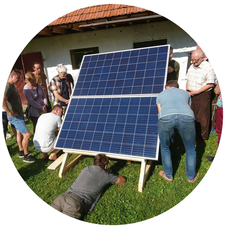
Short introThe goal is to build a low cost and simple off-grid photovoltaic (PV) system. PV refers to the solar energy that is used to generate electricity. Off-grid means that the system should operate without electrical grid connection. All the energy needed will be generated from the sun. The off-grid PV system consists of PV panels, power electronic converters and batteries. The solar panels capture the sun light and convert it into electricity, power electronic converters charge batteries and supply the load with that energy. The battery is needed to store excess energy for later usage. |
|
Complexity and cost of building and operatingBuilding and operating:
Medium (partially DIY, medium maintenance/operating complexity) Cost: High (>500 EUR) 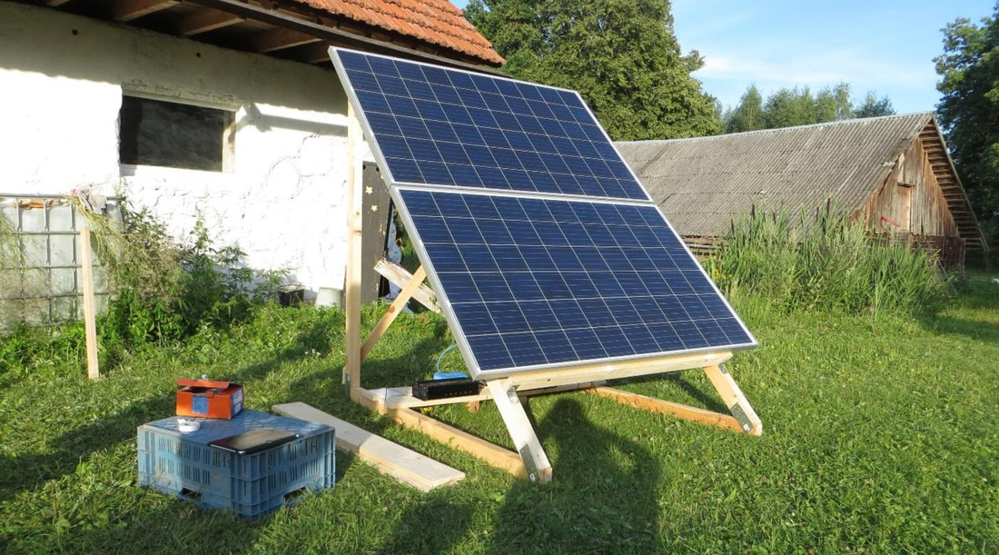
Fig.1: Example of PV-panel with wooden structure on the ground.
|
Materials, skills and tools requiredSkills:
It is mandatory to have basic understanding of electricity, voltage, current and resistance, and in some areas even connecting PV-panels will require the work of a licensed electrician. In order to calculate needed power and load one should know Ohms law. The basic theory is easy to learn from internet, and useful links to this are the following: “Voltage, Current, Resistance, and Ohm's Law” https://learn.sparkfun.com/tutorials/voltage-current-resistance-and-ohms-law/all "Electricity Basics” https://www.altestore.com/howto/electricity-basics-a18/ |
Important! Find out what you are allowed to do in your local area according to current regulation. |
|
Tools:
The following tools are needed for this project (Fig. 1, start from left): a multimeter (can measure DC voltage and current), wire cutters, pliers, different screwdrivers, carpenter knife (good for removing isolation from the cables), Soldering iron and tin solder wire. 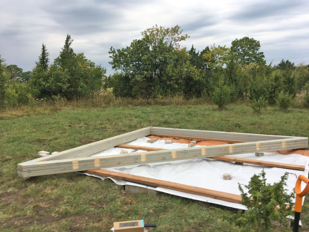
Fig.2: Tools needed for building the prototype.
In the designing phase it is recommended to use some energy meter (Fig. 2) for accurate consumption measurements. However, the consumption can also be calculated as shown later. Thus, it is an optional device.
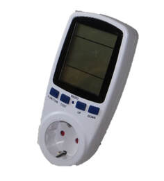
Fig.3: Energy meter for measuring consumption and power.
Materials used in the current project:
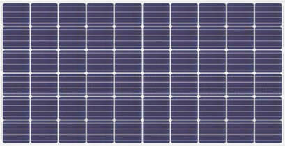
The key component of the system is the PV panel. In the current project two 275 W Chinese PV panels (CSUN275-60M) were used. The technical parameters are shown in Table 1. Table 1. Technical data of the PV panel CSUN275-60M Link: https://napssolar.ee/ , accessed 27.06.2020.. 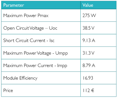
Fig.4: Table 1. Technical data of the PV panel CSUN275-60M
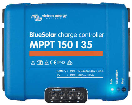
To charge batteries with the PV power and to maximize the performance of the PV panels a charge controller with maximum power point tracking (MPPT) is needed. In the current project the following charge controller Victron MPPT 150/35 was used. The technical parameters are shown in Table 2.
Table 2. Technical data of the charge controller Victron MPPT 150/35 Link: “victron mppt 150/35”, https://www.amazon.de/ , accessed 27.06.2020.. 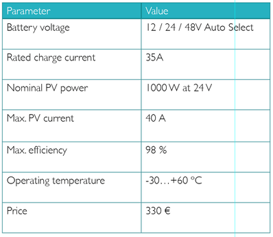
Fig.5: Table 2. Technical data of the charge controller Victron MPPT 150/35
An off-grid pure sine wave inverter is needed to convert battery voltage (DC) into a standardized grid voltage (AC). It is important to choose the pure sine wave (not just sine wave) inverter. This means that the output voltage will be pure sine wave 230 VAC that is accepted by all household devices.
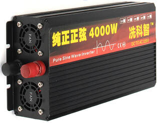
Table 3. Technical data of the pure sine wave solar inverter Link: “Pure Sine Wave Power Inverter 24 V”, https://www.aliexpress.com/ 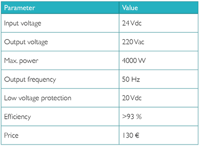
Fig.6: Table 3. Technical data of the pure sinewave solar inverter
To store excess solar energy and keep the system running also at night, batteries are needed. In this project deep cycle lead acid batteries were chosen.
Table 4. Technical data of the battery 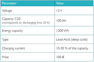
Fig.7: Table 4. Technical data of the battery
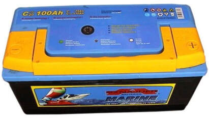
Fig. 8 shows small components and cables needed for the electric connections. The PV panels will be connected to the charge controller via special PV cables. The PV panels will be connected via MC4 connectors and batteries via battery terminals. The batteries must be connected through a fuse. For this purpose, a simple car fuse with sufficient current can be used.
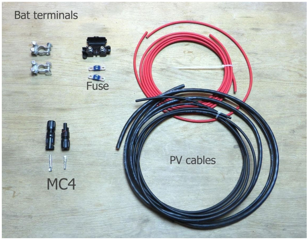
Fig.8: Small components and cables
|
Conclusions and errors to avoidBefore starting to buy the components, learn the basics of electricity. Then do your calculations and find out how many panels and how powerful converters you need, the number and type of the batteries etc. First, design the system on paper and then start building it. If the system is well designed and analyzed on the paper, then the building will be an easy and quick task. Before connecting batteries make sure you have fuses in place. Always connect first the charge controller with the batteries and only then with the PV panels. The charge controller is powered from the battery side and will not work properly with only PV panels connected. Check and double check the polarity and allowed battery voltage of the charge controller. Do not swap plus and minus terminals. Read the manual of the charge controller for more detailed instructions before connecting it. It can be easily damaged if connected in a wrong manner. Note that there could be a small spark at the battery terminals at the moment of connection. This is normal and means that the output capacitors of the charge controller were charged. The inverter is a less sensitive converter than the charge controller. However, following steps must be followed when connecting it. 1: First connect the batteries and only after that switch on the load. Note that there could be a small spark at the battery terminals at the moment of connection. This is normal and means that the input capacitors of the inverter were charged. Never connect two off-grid inverters in parallel or to the electric grid. It will destroy the inverter immediately. |
Life Cycle & Cost AnalysisPV-panels are made out of material that are mined and have a rather large footprint and energy-usage when produces. They are also harmful for eco-systems if not discarded in a responsible way. Recycling of PV-panels are becoming more common and available, and should be the natural choice once they are being discarded. Most components and materials in the panels can be recycled and re-used when processed in specialised factories.
Batteries are also often made out of mined materials that have rather large footprint and are harmful to eco-systems if not recycled. There are possibilities to re-use batteries for energy-storage that have had other usages before, and the development of new, more sustainable battery-technologies are constantly speeding up, as it is a central component of renewable energy systems. The total costs of the described PV system should be around 700 and 1300 €. It depends on the chosen components. The most expensive and short living component of the system is the battery. The total costs of the presented system were around 900 €. It could be reduced by choosing a cheaper charge controller. The life expectancy of the system is limited by the battery life. Currently used lead-acid batteries can take less than 1000 charging/discharging cycles while Li-ion batteries reach >2000 cycles. This results in a life expectancy around 5-15 years. The PV panels are required to have maximum degradation rate 1 % per year. This means that after 20 years 80 % of the nominal power could be achieved from the panel. However, today’s panels, with better technology and improved manufacturing techniques have degradation rate less than 0.4 % per year. That means that a panel manufactured today should produce 92 % of its original power after 20 years Link: “What Is the Lifespan of a Solar Pan”, https://www.engineering.com/DesignerEdge/DesignerEdgeArticles/ArticleID/7475/What-Is-the-Lifespan-of-a-Solar-Panel.aspx , accessed 27.06.2020. In general, the total life span of a PV panel today is around 30-40 years. Thus, the PV panels are the most durable components of the PV system. Power electronic converters have life expectancy around 10-20 years after what the electrolytic capacitors inside must be replaced. Theoretically, this replacement can be done by anyone who knows how to solder. |
|
Step by step guidelines for building the solution1. Calculations & DesignBefore starting with the building process, the off-grid PV system needs to be designed and planned properly. Although PV system can be built by yourself, most of the components (batteries, power electronic converters, etc.) must be purchased. Building without a plan could lead to expensive mistakes. There are different strategies how to design a PV system but in the current project following steps were used:
1. Estimate Local Solar conditions Before one can even think about building a PV system, it is important to know how much solar energy there is available on the site. For that purpose, EU has created an online photovoltaic geographical information system (PVGIS) Link: Photovoltaic Geographical Information System”, https://re.jrc.ec.europa.eu/pvg_tools/en/tools.html#PVP , accessed 28.06.2020. It can be used free of charge. PVGIS can simulate both: gird connected and off-grid system. To find out optimum PV panel slope at your location, first run grid connected simulation. Fill out following fields:
Click visualize results and see the data (Simulation outputs). PVGIS gives you optimum slope angle, yearly PV energy production and also graphically shows the monthly energy output. You can run the PVGIS off-grid simulation later when you have calculated your exact PV system parameters i.e. size of battery, power level and number of panels. PVGIS off-grid simulation shows you how much solar energy your system can capture and how much will be lost. Now you can fine tune your off-grid PV system by increasing the energy storage or reducing the number of PV panels. 2. Load and consumption estimation The second step in the case of any PV system is the estimation of load and consumption. By knowing the load, the needed power and number of PV panels, the required energy becomes defined. The easiest method for load estimation is to conduct some measurements with a simple energy meter (Fig. 3). Connect all devices which you plan to run off-grid to the energy meter and measure the needed energy and power levels over some period of time (1-5 days). If you have no electricity or no energy meter you can also calculate the needed electric power. First, create a list of devices you want to operate. Usually all household devices have a data plate with electrical parameters. If you cannot find it then check out the list of typical household appliances and their typical power ratings (in Watts) in internet Link: “Power Ratings (Typical) for Common Appliances”, https://www.altestore.com/howto/power-ratings-typical-for-common-appliances-a21/ , accessed 28.06.2020.. You can use this information to help you estimate the total amount of Watt-Hours that your alternative energy system needs to supply on an average day. The consumed energy over a time period can be calculated from the power as follows: where E is the energy, P is the electric power of the load, t is the operation time of the load. In the current project the load consisted from a water pump and a refrigerator. If the 300 W pump works 3.7 h per day it consumes about 1100 Wh energy. The 200 W refrigerator is expected to work about 4.5 hours/day and consume 900 Wh of energy. The total energy needed is 2000 Wh/day. The maximum power of the system is 500 W. 3. Storage Selection As a rule, the bigger the better. In off-grid PV system the size of the storage is strongly corelated with the living comfortability. Smaller storage simply means less energy at night or at cloudy days. However, the energy storage (battery) is also the most expensive component in the system. Thus, the selection of the size will be a trade of between price and living comfortability. First step would be to select right storage technology. In general, one should decide between Lithium and lead-acid battery. Lead-acid is cheaper but also has much lower efficiency and number of life cycles. Lithium has two times higher initial costs but lasts longer and works with greater efficiency. A good guide about technological differences and battery selection can be found from the internet Link: “Batteries: Lithium-ion vs AGM”, https://www.victronenergy.com/blog/2015/03/30/batteries-lithium-ion-vs-agm/ , accessed 28.06.2020.. Second step is to select suitable voltage. Higher voltage is better since it results in lower current and in cables with smaller diameter. Moreover, many the charge controllers accept multiple battery voltages. With twice higher voltage the same charge controller can process twice higher power. In practice, the chosen voltage depends on the system power as follows Link: “How to connect your batteries to make up a 24V or 48V system”, https://www.newenergyco-op.co.uk/blog/how-to-connect-your-batteries-to-make-up-a-24v-or-48v-system.html , accessed 28.06.2020.:
Multiple batteries can be connected in series to get higher voltage (recommended) but they can be also connected in parallel to get more current. Note that the energy content of the battery pack is not depending on the connection type. It is only defined by the chemistry inside the batteries. The energy content E of the battery can be calculated as: where Ubat is the battery nominal voltage, C20 is the rated capacity for 20 h discharge of the battery given in Ah. In the current project the storage should cover one day energy consumption 2000 Wh (see chapter Load and consumption estimation). Due to price limitation lead-acid batteries were selected. Two 100 Ah, 12 V deep cycle batteries were connected in series resulting in total energy content of 2400 Wh and voltage 24 V. This will cover the daily energy need. 4. Inverter Selection Inverter is a power electronic device which converts battery dc voltage into sinusoidal ac voltage. The inverter will be chosen according to load power and battery voltage. The inverter must always have some power reserve. How big power reserve is needed depends on the type of load. A rule of the thumb is to choose the inverter with 2-3 times bigger power rating than required by the load. In the current project the maximum expected power of the load was 500 W (see chapter Load and consumption estimation). Thus, the minimum requirement for the inverter is 1000 W. In the current project an inverter 4000 W was selected. 5. PV power and voltage selection The PV panel is a nonlinear energy source that has neither fixed voltage nor current. PV panel is insensitive against short circuit and open circuit. In both cases it delivers no power. The point of maximum power is somewhere between open circuit (no load) and short circuit (overload) point, as shown in Fig. 4. This so-called maximum power point (MPP) must be continuously tracked by the charge controller. 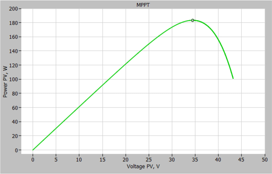
Fig. 9: Power vs. PV voltage graph.
The number of PV panels depends on the electric load. The peak PV power should reach at least the load level e.g. 1 kW load demands at least 1 kWp of PV power. However, the PV production heavily depends on the weather and is drastically reduced with clouds. Thus, it is common to install 10…20 % more PV power than required by the load. More PV panels compensate bad weather. Note that the PV voltage in MPP should be 7-10 V higher than the battery voltage. This is due to the fact that most of charge controllers on the market are step-down converters i.e. they cannot increase the voltage. If the MPP voltage (Vmpp) is lower than the battery voltage, then the charge controller can never extract maximum power from the PV panel.
In the current project maximum load power is 500 W (see chapter Load and consumption estimation). Two 275 Wp panels were selected. The minimum required MPP voltage is Ubat+10 = 34 V. The Umpp of the PV panel CSUN275-60M is 31.3 V (Table 1), which is lower than the minimum requirement. Thus, the panels had to be connected in series, which resulted in new MPP voltage 31.3x2 = 62.6 V. As a conclusion, in the current case the PV panels could not be connected in parallel due to the too low Umpp. 6. Charge Controller Selection There are two types of charge controllers: MPPT controller and PWM controller. PWM charge controller is a low-cost solution that suits best for small PV systems with moderate to high temperatures (45…75 ºC). In northern countries where solar irradiance fluctuates and the average temperatures are lower, MPPT controller is a better solution White paper: “Which solar charge controller: PWM or MPPT?”, https://www.victronenergy.com/upload/documents/White-paper-Which-solar-charge-controller-PWM-or-MPPT.pdf , accessed 28.06.2020.. Next criteria to consider are: Power of PV panels, open circuit voltage of PV panels (Uoc), battery voltage and charging current. In the current project PV power was 550 W, Uoc= 2x38.5=77 V (Table 1), Ubat = 24 V, max charging current Ppv/Ubat=550/24=23 A. According to this data a Victron energy MPPT controller was selected (Table 2). The Victron MPPT 150/35 charge controller supports PV voltage up to 150 V and battery charging current up to 35 A. 2. Building phase1. Building the frame
The frame can be built from timber, as shown in Fig.10: The dimensions and construction drawings are shown in Fig.11. 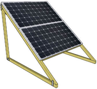
Fig.10: PV-panels on timber frame.
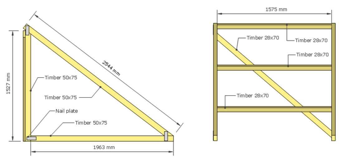
Fig.11: Dimensions of timber frame for two PV-panels
The list of timber and measures:
2. Electrical connections Electrical principle diagram is shown in Fig. 6. The system consists of two PV panels, the charge controller, two lead-acid batteries in series connection and inverter. Electric loads will be connected directly with the inverter. 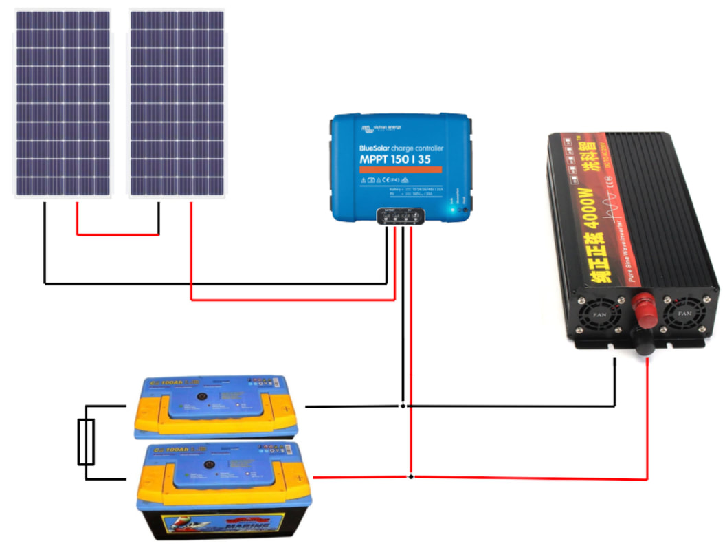
Fig.12: Electrical principle diagram of the prototype.
|
Videos
|
01: Introduction
|
02: About solar
|
03: The solar panel
|
|
04: Install/mount the panels
|
05: Place the panels
|
06: The connectors
|
|
07: Connecting cables on panel
|
08: Connecting two panels
|
09: The parts
|
|
10: To start
|
11: Connecting the batteries part 1
|
12: Connecting the batteries part 2
|
|
13: Adding the fuses
|
14: The charge controller
|
15: Connecting the inverter
|
|
16: Conclusion & Battery maintenance
|
|
Author of the contentReferencesThe following links can be found in connection to each relevant section in the description.
|
|
|
|
|